![]()
|
Title: |
Piping and Valves |
Doc. No. |
L-001 |
Annex |
C |
EDS |
NAF1 |
|
Project: NORSOK |
Company: |
Rev.Date: |
20.09.99 |
Rev: |
3 |
||
ASME B16.5, MSS-SP-44 and ASME B16.36 welding neck flanges.
a. Flanges shall be bored to pipe schedule (or wall thickness)
b. Outside cylindrical part of welding neck end of hub shall have Hmax as defined in fig. and table.
c. Gasket surface finish shall be according to ASME B16.5 for raised face (RF) flanges, but class 600 rating shall have maximum 250 micro inch finish.
d1. Maximum undertolerance of nominal pipewall thickness T, shall be 0.3 mm for MSS-SP-44 flanges when rating is higher than class 150.
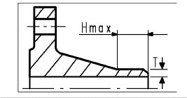
Hmax - TABLE (mm)
|
|
|
|
|
|
|
|
|
|
|
|
|
|
|
|
|
|
|
|
|
|
|
|
Rating |
NOM SIZE (in) |
|
|||||||||||||||||||
|
LB |
.5 |
.75 |
1 |
1.5 |
2 |
3 |
4 |
6 |
8 |
10 |
12 |
14 |
16 |
18 |
20 |
24 |
30 |
36 |
42 |
48 |
|
|
150 |
20 |
20 |
20 |
20 |
20 |
20 |
20 |
20 |
20 |
20 |
20 |
20 |
20 |
25 |
25 |
25 |
20 Note 2 |
||||
|
300 |
20 |
20 |
20 |
20 |
20 |
20 |
20 |
20 |
20 |
20 |
20 |
25 |
25 |
25 |
25 |
25 |
20 |
||||
|
600 |
20 |
20 |
20 |
20 |
20 |
20 |
20 |
20 |
25 |
25 |
25 |
25 |
30 |
30 |
35 |
35 |
|
||||
|
900 |
20 |
20 |
20 |
20 |
20 |
20 |
20 |
25 |
25 |
25 |
30 |
30 |
35 |
35 |
35 |
40 |
20 Note 1 |
||||
|
1500 |
20 |
20 |
20 |
20 |
25 |
25 |
25 |
30 |
30 |
35 |
40 |
40 |
45 |
50 |
50 |
60 |
|
||||
|
2500 |
25 |
25 |
30 |
35 |
40 |
50 |
55 |
80 |
80 |
120 |
120 |
|
|
|
|
|
|
||||
|
|
.5 |
.75 |
1 |
1.5 |
2 |
3 |
4 |
6 |
8 |
10 |
12 |
14 |
16 |
18 |
20 |
24 |
30 |
36 |
42 |
48 |
|
NOTES
1. Maximum under tolerance of welding end thickness not to exceed 0.3 mm
2. Stainless steel flanges, use Hmax = 10 mm for 30" through 42" pipe.
RTJ DIMENSION ABOVE 36"
RTJ ring and groove shall be according to ASME B16.20 ring No. (in table below), except that pitch diameter shall be according to table below:
|
RATING(lb) |
600 |
900 |
1500 |
|
NOM SIZE(in) |
|
42" |
|
|
RTJ pitch diam. P(mm) |
|
1124 |
|
|
Facing diam. K(mm) |
|
1226 |
|